

Next: Packet routing
Up: Vrouter validation
Previous: What happens when a
Contents
We can display a mount of informations about some entity by using the commands
dump table_name, where table_name can be VARP table, VIF table
of VRIP table.
- The VIF table : This table contains informations about the installed
interfaces in some entity. To display the VIF table we use the following command
: dump vif.
The informations provided by this table are the following :
Interface identifier, Interface IP address, Interface network mask, Network
broadcast address, Interface datalink and interface status ( up/down).
- The VARP table : This tables shows the VARP entries of some network
entity. To display the VRIP table we use the following command
: dump varp. The informations provided by this table are the following :
hardware address of the host in the same link , the corresponding IP address of
the entity, VARP entry age ( used to expire VARP entries and issue VARP SOL_REQ
message for renewing ).
- The VRIP table : This tables shows the VRIP entries of some network
entity. To display the VRIP table we use the following command
: dump vrip. The informations provided by this table are the following :
destination entity, next hop to destination, Flags (not used), metric ( because
we use a distance vector routing protocol ), routing entry age ( not used ).
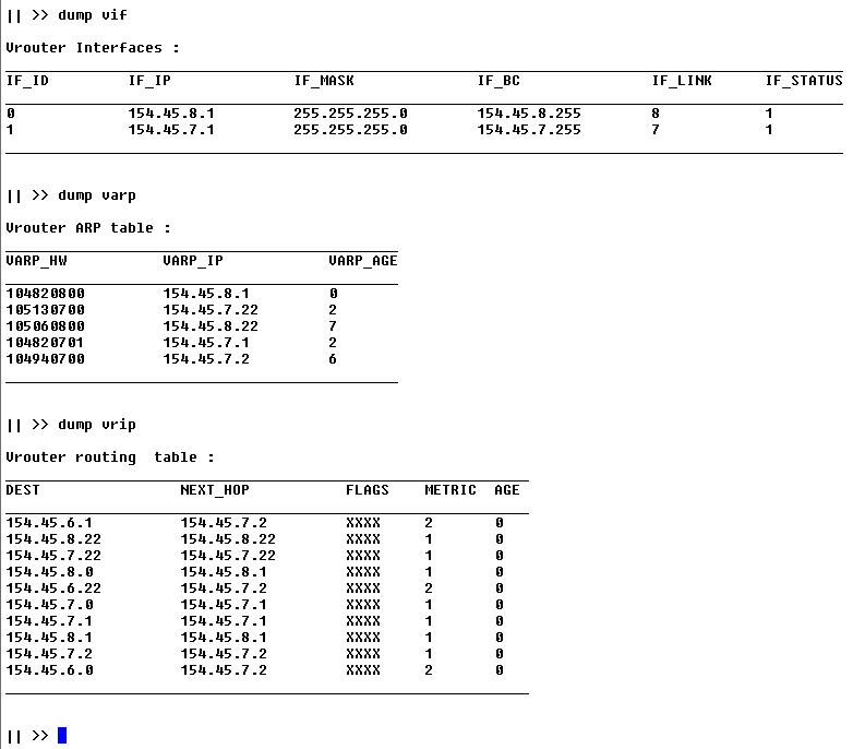
Figure 4.2:
GW 7-8 settings after network stabilisation.
|
|
We can see in the above figure that the routing table of the GW 7-8 has been
updated by the VRIP protocol. Indeed the routing table contains routes to
the network 154.45.6.0, reacheable through the gateway GW 6-7. We have also a
new route to the host 154.45.6.22 through GW 6-7. We can also see that we have a
number of direct routes to the entities connected to the same link as one of the
vrouter interfaces. These direct routes are generated automatically from VARP
requests ; when an entity receives a VARP message containing informations about
some other entity in the same link, a direct route to that entity is added to
the routing table.
Figure 4.3:
Host 8 settings after network stabilisation.
|
|
Figure 4.4:
Host 7 settings after network stabilisation.
|
|
Figure 4.5:
Host 6 settings after network stabilisation.
|
|
Figure 4.6:
GW 6-7 settings after network stabilisation.
|
|
5in


Next: Packet routing
Up: Vrouter validation
Previous: What happens when a
Contents
Last changed 2004-08-25.
Zrelli Saber. , Japan
Advanced Institute of Science and Technology, Shinoda-lab
zrelli@jasit.ac.jp
